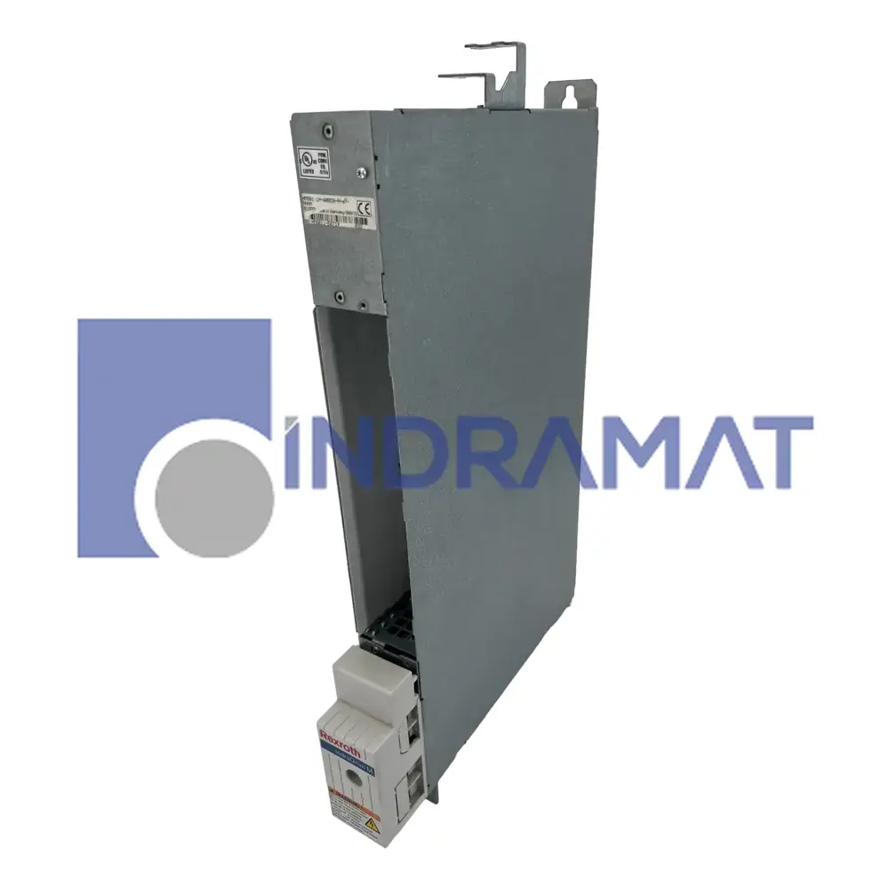
R911295323 (HMS01.1N-W0020-A-07-NNNN)
HMS Axis Inverters
Technical Specifications
Line Code
1
Design Code
1
Power Connections
A1, A2, A3
Max Current Rating
20A
Connectors
X5 and X6
Protection
Touch Guard
Nominal DC Bus Voltage
700VDC
Cooling Method
Internal Air Circulation
Certification
CSA Certified, UL Listed
Wiring Material
Class 1 Copper
Required Connection Cables
IndraDyn and IndraDrive connection cables
Input Control Voltage
24V +/-20%
Max Ambient Temperature (rated data)
40°C
Max Ambient Temperature (derated data)
55°C
Output Frequency Range
0-1,000Hz
Connector X5 use
Motor Connection
Connection Cable Cross-Sectional Area
1-4mm2
Grounding Terminal
Used for equipment grounding
Frequently Asked Questions
What is the intermediate circuit voltage range and how does it impact compatibility with the DC supply?
The inverter supports a DC bus (intermediate circuit) voltage between about 254-750 V, meaning your DC supply unit must stay within that range to avoid undervoltage or overvoltage shut-downs; spikes above the upper limit can stress components and reduce lifespan.
How does the short-circuit current rating of 42,000 A rms affect upstream electrical protection design?
Because the inverter can withstand high short-circuit currents, upstream protection devices (fuses, circuit breakers) must be rated and fast enough to handle fault currents without unnecessary trips yet still protect wiring and connected equipment. Coordination between rating of main supply cables, fuses, and the inverter’s withstand capacity is required to prevent selective tripping and fire risk.
What wiring cross-section and connector sizes are recommended for motor and control connections (connectors X5, X6), and how do they affect performance?
The motor power terminals (via X5) require fairly large copper conductor sizing to carry 20 A (or more for larger HMS models), with proper torque tightening to reduce contact resistance; undersized wiring increases voltage drop and heating. Connector X6 (for motor temperature sensors, holding brake etc.) uses smaller wires, but improper connections here can lead to faulty feedback or safety issues.
How does the absence of an internal power supply (“Not Equipped”) affect system design for control-voltage supply?
Since no internal auxiliary power supply is built-in, you must provide an external clean 24 V source (±20%) for control logic and sensors; any dips or noise on that supply may cause erratic behavior or shutdowns. Proper filtering, backup, and ensuring voltage stability under load are therefore essential.
How do load profile and duty cycle affect how the HMS01.1N model should be selected relative to motors with frequent starts-stops or varying torque?
Motors with frequent starts/stops or high inertia loads produce high peak currents; the drive’s thermal time constant means repeated peaks will accumulate heat, potentially triggering current limiting unless the inverter is oversized. For such duty cycles, either choose a model with higher max/current rating, or ensure cooling and control profiles are set up to limit peak current duration.
Common Misspellings
HMS 01.1N-W0020-A-07-NNNN
HMS01-1N-W0020-A-07-NNNN
HMS011NW0020A07NNNN
HMS1.1N-W0020-A-07-NNNN
HMSO1.1N-W0020-A-07-NNNN
HMS01 1N W0020 A 07 NNNN
hms01.1n-w0020-a-07-nnnn
HMS011NW0020A07NNNN
HMS01 1N W0020 A 07 NNNN
Internal Product Review
The Bosch Rexroth HMS01.1N-W0020-A-07-NNNN is a HMS Axis Inverter with a nominal DC bus voltage of 700 V and a rated maximum current of 20 A. It features internal air cooling with an integrated blower and offers an output frequency range of 0 to 1,000 Hz. This controller is CSA certified, UL listed, and suitable for various industrial applications.


Shipping & Payment Options








Warranty

Repair
 We offer a repair service for the HMS01.1N-W0020-A-07-NNNN.
 Want to