Request a Quote
Buy Indramat Drives
Receive a quote NOW for all Indramat Drive replacement, repairs, and requests by requesting a quote here. You can also send an email to [email protected]. If you’d rather speak to a real person, call 1-919-899-0695. You’ll receive a quote within 15 minutes during business hours; your time is important and we put you first when offering industry leading, lightning-fast lead times.
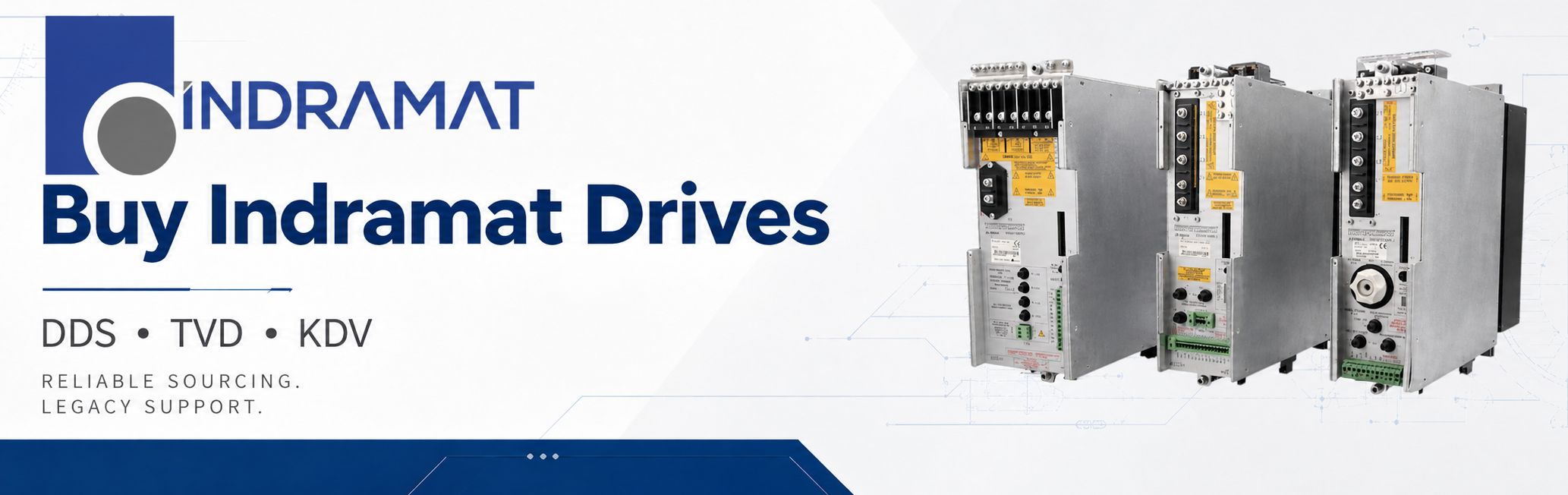
Indramat drives remain a major part of legacy automation systems used in machine tools, printing lines, packaging machines, textile equipment, robotics, handling systems, and other high-response motion control applications. When one of these units fails, the replacement process is rarely as simple as matching a broad series name. Cooling style, current rating, feedback format, bus voltage, supply module compatibility, firmware configuration, and installed plug-in modules can all affect whether a replacement will work correctly in the machine. Indramat-USA supplies replacement Indramat drives for maintenance teams, machine builders, integrators, and purchasing departments that need accurate part matching without unnecessary delays. We support legacy Indramat DDS drive controllers, TVD power supply modules, and KDV supply modules with options for replacement, repair, and surplus evaluation.
Indramat Drive Replacement and Repair Support
Indramat drive systems are modular, and many assemblies rely on a specific combination of supply modules, drive modules, firmware modules, plug-in cards, bus connections, and cabinet accessories. A DDS controller may require a matching feedback type and command communication configuration, while a TVD or KDV supply module must be matched to the correct DC bus power range, mains input, auxiliary modules, and control voltage requirements. Replacing a unit by appearance alone can create problems with current capacity, braking behavior, control voltage loading, and system readiness signals.
Indramat-USA focuses on practical replacement support for these legacy systems. We can quote replacement units when available, evaluate repair options for failed drives, and help customers identify whether the complete part number points to a standard module, a configured controller, or a special variant. For faster quoting, provide the complete part number exactly as shown on the rating plate, including suffixes such as firmware identifiers or special option codes.
DDS drive controllers are modular digital AC servo drive controllers used in Indramat DIAX systems. The DDS platform is built around a basic drive controller, plug-in modules, a software module, and firmware that defines the controller function. These drives are used with Indramat AC motors in compact multi-axis packages that share a common supply unit. DDS controllers must be selected carefully because the type code identifies key hardware details such as series, version, cooling method, rated current, motor feedback, communication interface, function ID, and firmware designation. DDS02.1 configurations may use digital servo feedback or resolver feedback, while DDS02.2 units use a feedback structure identified by the “B” feedback position in the type code. Cooling choices may include internal cabinet-air cooling, external cabinet-air cooling, or liquid cooling depending on the controller version and current range.
Common replacement drivers for DDS units include loss of output, intermittent axis faults, communication errors, feedback faults, overheated power sections, damaged connectors, failed plug-in modules, and missing or mismatched firmware modules. Because the configuration rating plate identifies the installed basic unit, software module, and plug-in modules, it is important to match more than just the front-facing DDS series number. Indramat-USA can quote replacement DDS controllers and secondary repair options when your production equipment depends on a specific legacy drive configuration.
Part Number | Cooling Style | Rated Current | Motor Feedback | Communication Configuration |
Internal cabinet-air cooling | 15 A | Digital servo feedback | Single-axis positioning configuration | |
Internal cabinet-air cooling | 50 A | Digital servo feedback | SERCOS configuration | |
Internal cabinet-air cooling | 100 A | Digital servo feedback | SERCOS configuration | |
External cabinet-air cooling | 100 A | Digital servo / resolver feedback type | SERCOS interface configuration | |
Internal cabinet-air cooling | 200 A | Digital servo / resolver feedback type | SERCOS interface configuration |
TVD power supply modules provide the regulated DC bus and control voltage support used by connected Indramat drive modules. TVD 1.3 is designed for direct connection to 3 x AC 380 to 480 V mains supply and provides a regulated 320 V DC bus. The TVD 1.3 platform is used where the system requires a compact supply module for drive packages up to a continuous mechanical output range of 12 kW. TVD 1.3 modules are available in 7.5 kW and 15 kW continuous DC bus power ratings. The 7.5 kW version provides 22.5 kW peak DC bus power for short acceleration periods, while the 15 kW version provides 45 kW peak DC bus power for short acceleration periods. These modules also include bleeder power handling, control voltage outputs, monitoring functions, and connections for compatible auxiliary devices.
TVD supply module replacement should account for the DC bus power rating, the 320 V DC bus requirement, the power connection module, the auxiliary bleeder arrangement, and control cabinet installation requirements. The TVD 1.3 system may be combined with NAM 1.3-08 or NAM 1.3-15 power connection modules, and separate components such as commutation chokes, buffer capacitors, and DC bus smoothing chokes may be required depending on the installation. Indramat-USA can quote replacement TVD modules and help customers identify whether the unit should be replaced, repaired, or evaluated as part of a larger drive power system.
Part Number | Continuous DC Bus Power | Peak DC Bus Power | DC Bus Voltage |
7.5 kW | 22.5 kW | 320 V DC | |
7.5 kW | 22.5 kW | 320 V DC | |
7.5 kW | 22.5 kW | 320 V DC | |
15 kW | 45 kW | 320 V DC | |
15 kW | 45 kW | 320 V DC |
KDV supply modules are used in modular Indramat AC drive systems where a supply module provides the DC link circuit voltage and control voltages for connected spindle and servo drive modules. The KDV 4.1 platform is designed for direct mains connection to 3 x AC 380 to 460 V, 50 to 60 Hz. It is used as the power supply foundation for systems where multiple drive modules are mounted to a single supply module.
KDV provides link circuit DC voltage for the power supply and the control voltages required by connected drive modules. It supports mains feedback, so braking energy from drives operating in generator mode can be fed back into the mains with reduced losses. The KDV 4.1 supply module also includes system monitoring functions that communicate with connected drive modules through the signal voltage bus. Indramat-USA can quote KDV replacement modules, repair services, and surplus options for customers maintaining legacy drive cabinets.
Part Number | Rated Current | Nominal Voltage | DC Bus Nominal Voltage | Nominal Voltage for Heatsink Blower |
30 kW power class | 3 x AC 380 to 460 V | 320 V DC | 230 VAC auxiliary / fan supply | |
30 kW power class | 3 x AC 380 to 460 V | 320 V DC | 230 VAC auxiliary / fan supply | |
30 kW power class | 3 x AC 380 to 460 V | 320 V DC | 230 VAC auxiliary / fan supply | |
100 A | AC 200 V | DC 300 V | AC 220 V | |
100 A | AC 220 V | DC 300 V | AC 115 V |
Indramat drive failures can be caused by age, heat, contamination, failed cooling fans, blown power components, degraded capacitors, damaged terminals, communication faults, feedback faults, firmware mismatch, or incorrect cabinet conditions. DDS drive controllers may show problems related to feedback signal integrity, SERCOS communication, plug-in module configuration, power section faults, or motor temperature monitoring. TVD and KDV supply modules may experience DC bus faults, bleeder overload, fan issues, control voltage loss, mains input problems, and shutdowns related to excess braking energy or equipment temperature.
Because these drive systems operate with high voltage and stored energy, troubleshooting and replacement work should be handled by qualified personnel. The safest and fastest replacement process is to identify the exact type code, check the connected power system and motor feedback configuration, and quote a replacement that matches the original unit’s function. Indramat-USA can provide replacement and repair options for legacy Indramat drive hardware used in demanding industrial environments.
Series | Display / Fault Code | Condition | Likely Cause | Possible Maintenance Solution |
TVD 1.3 | +24V / ±15V dark | Signal voltage fault | Missing or faulty mains input voltage for electronics supply | Check the mains fuse in the control panel. |
TVD 1.3 | +24V / ±15V dark | Signal voltage fault | Maximum signal voltage load exceeded | Disconnect the wire-ribbon connection to the drive modules, check voltages at X3, then disconnect signal-voltage loads and check for short circuits. |
TVD 1.3 | Bb1 dark | Fault stored in supply module or drive system | Fault in supply module | Check the remaining diagnostics displays on the supply module. |
TVD 1.3 | Bb1 dark | Fault stored in supply module or drive system | Drive module fault | Check the diagnostic display of the drive module. |
TVD 1.3 | Bb1 dark | Fault stored in supply module or drive system | Signal voltage bus connection fault | Check the bus cable at X1 and confirm the end connector is properly installed. |
TVD 1.3 | MAINS dark | Power supply fault | Main fuse actuated, missing mains phase at X7, or mains voltage too low | Check the main connection; rated value is 3 x 380–480 VAC ±10%. |
TVD 1.3 | POWER dark | Mains contactor not on or DC bus fault | Mains contactor not on | Check the circuit at X2/6 using +24 VL against 0 VL. |
TVD 1.3 | POWER dark | Mains contactor not on or DC bus fault | DC bus smoothing choke missing or incorrectly connected | Check the smoothing choke connection between X7/1L+ and X7/2L+. |
TVD 1.3 | POWER dark | Mains contactor not on or DC bus fault | Faulty rectifier | Replace the unit. |
TVD 1.3 | I-FAULT flashing | Fault not stored | Short circuit present during power-up in the unit, drive module, cable, or motor | Check the TVD, connected drive module, motor power cable, and motor before restarting. |
TVD 1.3 | I-FAULT red | Fault stored; shutdown due to overcurrent in power section | Defective drive module, damaged motor power cable, motor short circuit, or disconnected DC bus smoothing choke | Remove conductor rails to the drive module, check the drive module, motor power cable, motor, and DC bus smoothing choke, and replace components as needed. |
TVD 1.3 | I-FAULT red | Fault stored; shutdown due to overcurrent in power section | Short circuit inside the TVD unit | Replace the unit. |
TVD 1.3 | P-FAULT flashing | Warning | Bleeder fully loaded; braking power may not continue to rise | Reduce braking demand before the unit trips. |
TVD 1.3 | P-FAULT red | Fault stored; shutdown due to bleeder overload | Braking power of the drive is too high | Check drive energy content, reduce drive speed, increase load cycle time, and evaluate the BVW bleeder pre-warning contact. |
TVD 1.3 | P-FAULT red | Fault stored; shutdown due to bleeder overload | Defective bleeder or internal unit fault | Replace the unit. |
TVD 1.3 | T-FAULT flashing | Warning | Heatsink temperature too high; power will switch off within 30 seconds | Reduce load and check cooling/ambient conditions before shutdown occurs. |
TVD 1.3 | T-FAULT red | Fault stored; shutdown due to excessive heatsink temperature | Unit overloaded or ambient temperature too high | Check load and ambient temperature, and evaluate the TVW temperature pre-warning contact. |
TVD 1.3 | U-FAULT red | Fault stored; shutdown due to excessive DC bus voltage | Mains voltage too high | Check mains voltage; rated value is 3 x 380–480 VAC ±10%. |
TVD 1.3 | U-FAULT red | Fault stored; shutdown due to excessive DC bus voltage | Internal unit fault | Replace the unit. |
KDV 4.1 | [1] Electronics not being supplied | Electronics supply fault | Fuse F3 or F4 defective, or lead interrupted | Check voltage at X10a for 220 VAC and check fuses F3 and F4. |
KDV 4.1 | [2] No controller voltage | Signal/controller voltage fault | Fuse F3 or F4 defective, maximum signal-voltage load exceeded, or link circuit current below 180 VDC after mains failure | Release bus connections to drive modules, measure signal voltages, and check fuses F3 and F4. |
KDV 4.1 | [3] Power not on or interrupted | Mains/power feed fault | No correct rotational field at X9 or missing phase at X9 | Check power at X9 for 3 x 380–460 VAC and check rotational field at X9. |
KDV 4.1 | [4] Power not on or interrupted; link circuit fault | Link circuit fault | No correct rotational field at X9, missing phase at X9, link circuit current below 200 VDC, or link circuit smoothing choke not connected or incorrectly connected | Check mains feed at X9, check rotational field, remove busbars to drive modules and measure link circuit voltage at X9 L+ and L-, then check link circuit choke connection. |
KDV 4.1 | [5] Powering down due to excessive braking energy | Bleeder/braking energy fault | Excessive stored energy in drives during braking from E-stop or mains failure, defective bleeder resistor, or KDV fault | Check energy content of the drives and use delayed powering down during E-stop where required. |
KDV 4.1 | [6] Shutdown due to excessive equipment temperature | Thermal fault | Fan not connected or defective, F6/F7/F8 fuse defective, dirty heatsink, KDV overload, or excessive ambient temperature | Check fan and fuses F6, F7, and F8; clean heatsink; check load; check ambient temperature; test the TVW contact. |
KDV 4.1 | [7] Shutdown due to overcurrent | Power section overcurrent | Defective drive module, short circuit in KDV 4, excessive mains inductance, damaged motor power cable, or motor winding fault | Check drive modules, associated motors, and motor cables; check mains feed and mains transformer. |
KDV 4.1 | [8] Shutdown due to earth leakage | Ground/earth fault | Defective drive module, damaged motor power cable, or short circuit in motor housing | Check the drive module with its associated motor and cables. |
DDS02.1 / DDS02.2 | Status display / warning and error messages | DDS controller warning or error indication | DDS manuals provided identify the status display and reset key but do not provide a fault-code remedy table | Use the DDS status display to confirm that an error is present, reset only after the fault condition is corrected, and cross-check the connected supply module, motor feedback, motor power cable, and plug-in module configuration. |
Request a Quote for Indramat Drives
For pricing, availability, repair options, or surplus evaluation, contact Indramat-USA with your complete part number. Include photos of the rating plate, the front of the unit, the cabinet layout, and any visible fault display. This helps confirm the correct replacement and reduces the chance of ordering a unit with the wrong current rating, cooling style, feedback type, or power configuration.
Call 919-443-0207 today or send an email to [email protected] to quote Indramat DDS drive controllers, TVD power supply modules, and KDV supply modules. Replacement, repair, and quote-both options are available depending on your downtime requirements and equipment condition.
Frequently Asked Questions
What information is needed to quote a replacement Indramat drive?
The best information to provide is the full part number from the rating plate, clear photos of the unit, the cabinet layout, and any fault or diagnostic display shown on the system.
Can DDS drive controllers be replaced by matching only the DDS series?
What is the difference between TVD and KDV supply modules?
Are repair options available if a replacement drive is not in stock?
What are common failure signs in Indramat drives?
Does Indramat USA carry and support obsolete or legacy parts?
How long is an Indramat USA quote valid for?